Sketchfab presentation

With my models finished, I wanted to upload one of them to Sketchfab. I had an issue with this process, because the official plugin for Cinema 4D was not working for some reason. I even contacted the Sketchfab support and my tutor, James about it. After a few suggestions, I did some research and exported the file manually as .FBX, keeping all substances, textures and specifications of the model.

Zrzut ekranu 2017-12-13 o 15.32.15

The only issue I had after uploading it to Sketchfab was odd lighting and lack of transparency within the glass walls of the box.

Zrzut ekranu 2017-12-13 o 13.33.58

Sketchfab turned out to be an amazing tool, which lets the user adjust many values/settings and even add post-render effects, such like noise or depth of field. That helped me to fix the transparency settings for the glass and replace the lights to different positions and colours. It gave the scene an all-new look which I really like. I used Screenshots tab in Sketchfab Experiments Lab to save high resolution images of different perspectives of my model and added some extra noise in Adobe Photoshop.

https://sketchfab.com/models/8b30ff4c7b7a41ecb88b8318ad02c095

butterflies1butterflies2butterflies3butterflies4butterflies5

Butterfly model

Before final submission, I’ve given myself a task of completing one final 3D composition, this time related to the emissive light and inspired by the shape from Mateusz Lengling. I wanted to create something at least slightly connected to one of the compositions that I will be making in the next term.

FinalButterfliesbutterflies3butterflies2

I’ve created a box made of glass, glowing, fractured and emissive surfaces. Inside, I’ve placed a few butterfly models. Each of the butterflies is a copy of one main model, consisting of the 4 separate wing segments, antennas and the body.

Zrzut ekranu 2017-12-12 o 11.57.10

“Motyl” stands for butterfly in Polish, “czulki” for the antennas, and “trzon” for the core. It’s not very clear but in my workflow it’s sometimes just easier to use the native language. The core is made of an edited capsule, with flattened endings and for the wings, I’ve used a combination of the Bezier Pen tool and Extrude, to fill the shape. In the past, I had big problems with filling the outline, as it would always create weird polygons, which I couldn’t edit. One of the sources which I can’t remember, explained that it’s only XY camera view, which allows to make Pen tool outlines and Extrude them without any issues. After this step, I used a Symmetry effector and Split, to make both wings separate segments. Antennas are a result of simple Bezier + Sweep. You can’t really see the effectors on the object list, as I used the “Current state to object” option, to make the list a bit more organised. The walls of the box are made of simple cubes.

In terms of materials, I used three main variations:

Zrzut ekranu 2017-12-12 o 12.13.32

Zrzut ekranu 2017-12-12 o 12.15.33

Zrzut ekranu 2017-12-12 o 12.14.50

– Material 1 for two sides of the box, with Luminance and Color on. In the Color section, I’ve applied a marble texture, which is barely visible, but adds that subtle detail, when you zoom in

– Material 2 for two other sides, which is meant to mimic real glass, which is also fractured with the Voronoi Fracture effector

– Material 3 for the Butterflies with marble texture and bump map that I’ve assembled in Adobe Photoshop. I also added a Displacer in order to add the imperfections to the surface.

I then simply copied the butterfly model multiple times and changed the wing angle, to add dynamism and diversity. There are also two area lights adding some extra luminosity and luminance intensity.

The element that I wanted to improve but didn’t have enough time for was more random placement of the texture on wings, which looks a bit repetitive.

Zrzut ekranu 2017-12-12 o 12.33.21

Making a 3D model with various techniques

I feel like I have learned a lot during this term and decided that it is the right time to apply some of the skills and create something strongly relating to what my final project aim will be. Back in November, I’ve made an initial image of Travis Scott’s head model, learning from the low poly tutorial. Videos in my last two posts had a great impact on my modeling knowledge and explained some tools which turned out to be perfect for this model. Especially the Line Cut tool.

Starting from the beginning, I used the hair from the previous model, as I was really happy with how it came out. As explained in the article linked above, I used the Loft tool, changing the direction, size and angle with every next segment (I will explain the material applied later in the post).

Zrzut ekranu 2017-12-07 o 12.50.27

I really wasn’t happy with how the head itself came out. I used a Capsule and deformed it, but it wasn’t the effect and shape I was looking for. Even after applying the Polygon Reduction. With a much better knowledge of the tools available to me, I started off with a capsule again (with reduced number of segments), but this time, I used a reference image. As it wasn’t meant to be perfectly accurate, I just put my phone on the side with the front photo from my earlier post, for a better idea of the head shape.

I used a Live Selection tool with the “select only visible elements” option off, to make sure I get all the points behind too. The display mode was set to Lines so I could see all of them clearly.

Zrzut ekranu 2017-12-07 o 13.11.56

Then, I used the mentioned Line Cut tool. It gave me a great freedom with shaping up the capsule by creating lines crossing each other, and in result making more points to operate with.

Zrzut ekranu 2017-12-07 o 13.19.03

I have also made small capsules with polygon reduction for the eyes.

I then applied the Voronoi Fracture and played around with the point distribution/number and seed to obtain a satisfying effect:

Zrzut ekranu 2017-12-07 o 13.56.57

When I felt that the mesh is ready, I then focused on the materials. I found an interesting video on how to make Rock-Asteroids. It also covered the material creation. With my own small tweaks, I made a material consisting of Colour, Bump and Displacement with Wavy Turbulence and Blistered Turbulence noises as textures. I made the eyes a tiny bit darker so they stand out.

Zrzut ekranu 2017-12-07 o 14.06.56

Then I first rendered it with some default light and no background.

Zrzut ekranu 2017-12-07 o 14.13.32

The last two steps were:

– creating a realistic lighting with a free HDRI image I found from the internet, but making it invisible to the camera (also setting the renderer to Physical and adding Global Illumination in settings)

– finding appropriate background to complement the light

Zrzut ekranu 2017-12-07 o 14.23.27

pexels-photo-38326

During these steps, a tutorial about the lighting from one of my previous posts was particularly useful.

Final result (as you can tell, it was heavily inspired by Timothy Saccenti):

Trav

Fundamentals revision #2 – Polygon + Subdivision Surface Modeling

The polygon modeling tutorial covered a lot of basics that I have gone through, but some of them helped me a lot with creating a more complex 3D model that I will present in the next post.

Topics covered:

– loop selection

– path selection tool

– invert selection

– line cut

– loop cut

– ring selection

– connect points and edges

– close polygon hole

– bridge (click and drag on the points, then select other points —> connection between them is being created)

It also covered and helped me to solve and issue I had in the past. When I selected and moved the polygons with a Live Selection tool, they seemed to be disconnected from the rest of the object (in the case of a cylinder).

Zrzut ekranu 2017-12-04 o 23.15.04

Solution: cylinder uses Caps, which are disconnected. We have to use command called ‘Optimize’, which connects those points together. It is also a good way to get rid of unused points in our model.

Zrzut ekranu 2017-12-04 o 23.23.54

Stitch and Sew – this is a new tool to me, which is used to reduce the details of my geometry. Once the object is converted to be editable. I’m doing it by dragging one point onto another with this tool on.

Zrzut ekranu 2017-12-04 o 23.36.43Zrzut ekranu 2017-12-04 o 23.36.52

Dissolve – when applied with a few polygons selected, it removes the edges between them.

After this tutorial, I went through the Subdivision Surface modeling introduction.

Zrzut ekranu 2017-12-06 o 13.23.12

There is no way around it if we want to model realistic looking objects.

Zrzut ekranu 2017-12-06 o 14.16.59

I learned the Q shortcut to switch in between the Subdivision and normal mode. In order to test it, I’ve made a regular cube and removed a few surfaces to have some edges standing out. I then made it a child of the Subdivision Surface effector and observed how the edges become rounded

 Zrzut ekranu 2017-12-06 o 14.33.06Zrzut ekranu 2017-12-06 o 14.33.16  Zrzut ekranu 2017-12-06 o 14.34.59

There’s also another way to adjust the edges – Weighting. It’s based on selecting the edge with and edge loop selection tool and holding down the dot (point) button to then move the cursor left and right to adjust the weight. Clicking on the Weight icon next to the object name reveals a heat map, which shows the weight around the edges.

Zrzut ekranu 2017-12-06 o 16.15.46 Zrzut ekranu 2017-12-06 o 16.16.03Zrzut ekranu 2017-12-06 o 16.53.02 Zrzut ekranu 2017-12-06 o 17.59.55

The overall aim of my project is to be diverse within modeling and learn a lot of new techniques. Even though my final model idea probably won’t involve Sub-D, it is essential to have a knowledge about this area too.

Fundamentals revision with examples #1 – Spline Modeling

Before entering the last week of my project development and summing up what I have learned, I decided to go through tutorials explaining different fundamental techniques of modeling. Spline modeling was the first one.

Spline Modeling:

– Non-uniform objects

– Organic shaped objects

– Advanced base objects

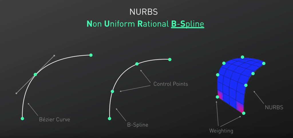
Using 3D spline to create NURBS-object

Zrzut ekranu 2017-12-03 o 23.13.21

NURB – Non Uniform Rational B-Spline

Zrzut ekranu 2017-12-03 o 23.25.45

It’s important to understand B-Splines in order to understand sub-division modeling.

When we use the B-Splines, it’s essential to use one of the side views or the front view.

Control points in the B-spline are not integrated with the spline (difference between Bezier and B-Spline).

First practice: Using the Line Cut tool (in tutorial a “Knife Tool” is being used, but it seems to be an older version of Line Cut), I added two points to a perfect 90 degree corner. When I then changed the spline type from Linear to B-spline, the points created a rounded angle.

Zrzut ekranu 2017-12-03 o 23.44.48

When the edge is hard and we want a more subtle transition between the points, we can right click and select “Soft Interpolation”

Zrzut ekranu 2017-12-03 o 23.53.51Zrzut ekranu 2017-12-03 o 23.54.22

We can also right click and select “Equal Tangent Length”.

Zrzut ekranu 2017-12-04 o 00.00.59Zrzut ekranu 2017-12-04 o 00.01.16

We can also use “Create Outline” to make a perfect outline of our spline:

Zrzut ekranu 2017-12-04 o 00.06.56

Zrzut ekranu 2017-12-04 o 00.08.15

You always have to make the splines children of the generators.

When we use the Extrude generator, we can still make the spline editable and move the points (or for example use the Line Cut and apply Soft Interpolation).

Zrzut ekranu 2017-12-04 o 00.21.49 Zrzut ekranu 2017-12-04 o 00.22.01 1Zrzut ekranu 2017-12-04 o 00.25.53

I have already used a Lathe tool in the past, but I felt that revision is necessary. First off, we have to make sure that the start point is perfectly positioned in the middle.

Zrzut ekranu 2017-12-04 o 00.30.17

We can then complete the half of the glass shape and give it some thickness by creating an outline. Adding the Lathe tool and making the spline a child of it will create a perfectly rounded shape. I thought it’s a good chance to create a composition connecting a few other tutorials.

Zrzut ekranu 2017-12-04 o 15.38.39Zrzut ekranu 2017-12-04 o 16.12.22wineglass

Apart from the wine glass shape made of the Lathe + Spline, I applied a gradient-based background and the Voronoi Fracture (with Time effector).

The last parts of the video focused on using Sweep, where we create one base shape (like a circle) and make it children of the Sweep with our spline. Then, it explained something I have already practiced in the Travis Scott head model (hair) – using the Loft to connect the splines.

Zrzut ekranu 2017-12-04 o 17.02.56

Round up:

Zrzut ekranu 2017-12-04 o 16.56.28